


Digital code locks are very popular in electronics, where you have to enter a certain “code” to open Lock. This type of Lock requires a Microcontroller to compare the entered code with the predefined code to open the Lock.
We have already built these types of digital locks using Arduino, using Raspberry PI and using Microcontroller 8051. But today here we are building Code Lock without any Microcontroller.
In this simple circuit, we build 555 IC timer based on code lock. In this lock, there will be 8 buttons and you have to press four specific buttons simultaneously to unlock the Lock. The 555 IC is configured as a monostable vibrator here. Basically, in this circuit, we will have an LED at the output pin 3 which lights up when it is triggered by pressing those four specific buttons
The LED stays on and then goes off automatically. The on-time can be calculated with this 555 monostable computer. The LED represents the electric lock here, which remains locked when there is no current and is unlocked when passing through it. The combination of four specific buttons is the “Code”, which must open the Lock.
Required Components
- +5V Supply Voltage
- 555 Timer IC
- 470Ω resistor
- 100Ω resistor (2 pieces)
- 10KΩ resistor
- 47KΩ resistor
- 100µF capacitor
- LED
- Push Button (8 pieces)
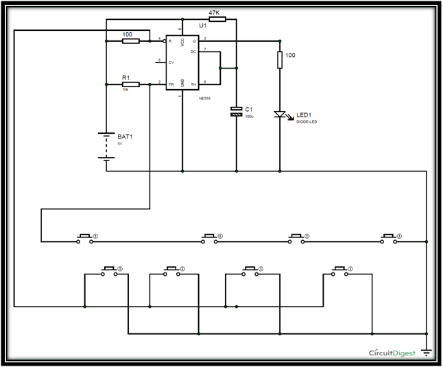
Circuit Diagram

Working Explanation
- As mentioned earlier, here the 555 IC is configured in the Monostable Multivibrator mode. Therefore, once the shutter is released by pressing the Push button, the LED will illuminate and the output will remain high until the capacitor is connected to PIN6 loads at the peak value. The time for which OUTPUT will be high can be calculated according to the formula below.
T = 1.1*R*C
- So according to values in our circuit, T = 1.1*47000*0.0001 = 5.17 seconds.
- So the LED will be ON for 5seconds.
- We can Increase or Decrease this time by changing the capacitor value.
- This length of time is the period for which the Lock will remain open after entering the correct code or pressing the correct keys. Therefore, we need to allow enough time for the user to enter through the door after pressing the correct keys.
- Now we know that in 555 Timer IC, regardless of TRIGGER, if the RESET PIN is pulled down, the output will be LOW. So here we will use the Trigger and Reset pins to build our Code Lock.
- As shown in the circuit, we used Push Buttons in the wrapped mode to confuse unauthorized access. As in the circuit, the upper level buttons are “Linkers”, all must be pressed together to apply TIGGER. The buttons on the BOTTOM layer are all RESET or “Mines”; if you press even one of them, the RESULT will be LOW even if LINKERS is pressed simultaneously.
- Note that Pin 4 is the reset pin and Pin 2 is the trigger pin in timer IC 555. The grounding pin 4 will reset 555 IC, and the grounding pin 2 will trigger the large output. So, to get the output or open the Code Lock, you must simultaneously press all the buttons in the TOP layer (links), without pressing any buttons in the bottom layer (mines). With 8 buttons we will have 40K combinations and if the correct LINKERS is not known, it will take forever to get the correct combination to open the Lock.
Internal working of the circuit
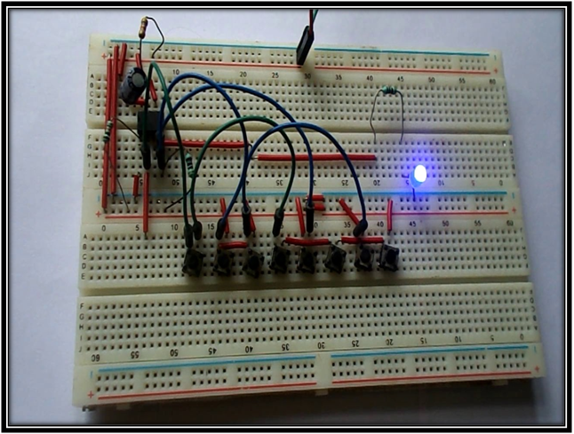
- Suppose the circuit is connected to the bread plate, according to the circuit diagram and given power. Now the LED will be off because TRIGGER is not given. The TRIGGER pin in the chronometer chip is very sensitive and causes the output to be 555. A low logic on the TRIGGER 2 pin SET the flip-flop inside the 555 TIMER and we get High Output and when the trigger pin is granted, the logic is high. , the output remains LOW.
- When all the keys in the Top Layer (Linkers) are pressed together, then only the trigger pin is grounded and we get Exit as HIGH and the lock is unlocked. However, this high step cannot be maintained long after the shutter is triggered.
- Once LINKERS is released, the HIGH output stage depends only on the charge time of the capacitor connected between Pin 6 and ground.
- Therefore, the lock will remain unlocked until the capacitor is charged. The capacitor once reaches a voltage level that it discharges through the 555 THRESHOLD (PIN6) pin, which pulls OUTPUT down and the LED goes off as the capacitor discharges.
- This is how 555 Timer IC works in Monostable Mode.
- That’s how this electronic lock works, you can replace the LED with the actual electric door lock using a relay or transistor.
Applications
- It is used in Door Lock Systems
- It is used in Banks
- It is used in Museums
- It is used in Laboratories
- It is used in Industries
Special Thanks To Solanki Hetarth & Raval Harshil