


Thyristor Commutation Techniques
Most of the converter equipment and switch-mode power supplies use power electronics components like SCRs, MOSFET and other power semiconductor devices for high frequency switching operations at high-power ratings. Consider the SCRs that we use very frequently as bistable switches in several applications. These SCRs use switches needed to be switched on and off. For switching on the SCRs, there are some SCR turn on methods called as SCR triggering methods. Similarly, for switching off SCRs, there are methods called as SCRs commutation techniques. Before discussing about SCR commutation techniques, we must know something about the SCRs basics such as SCR, SCR operation, different types of SCRs and SCR turn on methods.
What is Thyristor ?
Two to four lead semiconductor devices consisting of four layers of alternating N and P-type materials are called as Thyristors. These are generally used as bi-stable switches which will conduct only when the gate terminal of Thyristor is triggered. Thyristor is also called as silicon controlled rectifier or SCR.
What is SCRs Commutation Techniques ?
As we have studied above, a SCR can be turned on by triggering gate terminal with low voltage short duration pulse. But after turning on, it will conduct continuous until the SCR is reverse biased or the load current falls to zero. This continuous conduction of SCRs causes problems in some applications. The process used for turning off a SCR is called as commutation. By the commutation process, the SCR operating mode is changed from forward conducting mode to forward blocking mode. So, the SCR commutation methods or SCR commutation techniques are used to turn off.
The commutation techniques of SCRs are classified into two types:
- Natural Commutation
- Forced Commutation
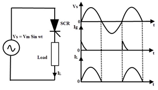
Natural Commutation
Generally, if we consider AC supply, the current will flow through the zero crossing line while going from positive peak to negative peak. Thus, a reverse voltage will appear across the device simultaneously, which will turn off the SCR immediately. This process is called as natural commutation as SCR is turned off naturally without using any external components or circuit or supply for commutation purpose.

Natural commutation can be observed in AC voltage controllers, phase controlled rectifiers and cycloconverters.
Forced Commutation
The SCR can be turned off by reverse biasing the SCR or by using active or passive components. SCR current can be reduced to a value below the value of holding current. Since, the SCR is turned off forcibly it is termed as a forced commutation process. The basic electronics and electrical components such as inductance and capacitance are used as commutating elements for commutation purpose.
Forced commutation can be observed while using DC supply; hence it is also called as DC commutation. The external circuit used for forced commutation process is called as commutation circuit and the elements used in this circuit are called as commutating elements.
Classification of Forced Commutation Methods
The forced commutation can be classified into different methods as follows:
- Class A: Load Commutation
- Class B: Resonant Pulse Commutation
- Class C: Complementary Commutation
- Class D: Impulse Commutation
- Class E: External Pulse commutation
- Class F: line commutation
Class A: Load Commutation
Class A is one of frequently used SCR commutation techniques. If SCR is triggered or turned on, then anode current will flow by charging capacitor C with dot as positive. The second order under-damped circuit is formed by the inductor or AC resistor, capacitor and resistor. If the current builds up through SCR and completes the half cycle, then the inductor current will flow through the SCR in the reverse direction which will turn off SCR.


After the SCR commutation or turning off the SCR, the capacitor will start discharging from its peak value through the resistor is an exponential manner. The SCR will be in reverse bias condition until the capacitor voltage returns to the supply voltage level.
Class B: Resonant Pulse Commutation
This is a type of commutation in which a LC series circuit is connected across the SCR. Since the commutation circuit has negligible resistance it is always under-damped i.e., the current in LC circuit tends to oscillate whenever the SCR is on.

Initially the SCR is off and the capacitor is charged to V volts with plate ‘a’ being positive. the SCR is turned ON by giving a gate pulse. A current IL flows through the load and this is assumed to be constant. At the same time SCR short circuits the LC combination which starts oscillating. A current ‘i’ starts flowing in the direction shown in figure. As ‘i’ reaches its maximum value, the capacitor voltage reduces to zero and then the polarity of the capacitor voltage reverses ‘b’ becomes positive). When ‘i’ falls to zero this reverse voltage becomes maximum, and then direction of ‘i’ reverses i.e., through SCR the load current IL and ‘i’ flow in opposite direction. When the instantaneous value of ‘i’ becomes equal to IL , the SCR current becomes zero and the SCR turns off. Now the capacitor starts charging and its voltage reaches the supply voltage with plate a being positive
.
Class C: Complementary Commutation
In the class C commutation techniques of SCR there will be two SCRs. One SCR is considered as main SCR and the other as auxiliary SCR. In this classification both may act as main SCRs carrying load current and they can be designed with four SCRs with load across the capacitor by using a current source for supplying an integral converter.


If the SCR T2 is triggered, then the capacitor will be charged up. If the SCR T1 is triggered, then the capacitor will discharge and this discharge current of C will oppose the flow of load current in T2 as the capacitor is switched across T2 via T1.
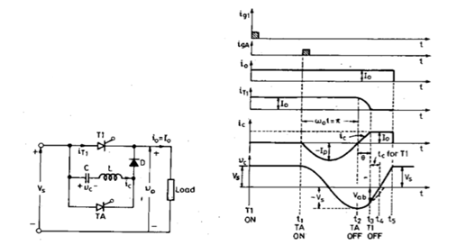
Class D: Impulse Commutation
The class C and class D SCR commutation techniques can be differentiated with the load current in class D: only one of the SCR’s will carry the load current while the other acts as an auxiliary SCR whereas in class C both SCRs will carry load current. The auxiliary SCR consists of resistor in its anode which is having resistance of approximately ten times the load resistance.

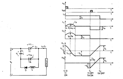
By triggering the Ta (auxiliary SCR) the capacitor is charged up to supply voltage and then the Ta will turn OFF. The extra voltage if any, due to substantial inductance in the input lines will be discharged through the diode-inductor-load circuit.
If the Tm (main SCR) is triggered, then the current will flow in two paths: commutating current will flow through the C-Tm-L-D path and load current will flow through the load. If the charge on the capacitor is reversed and held at that level using the diode and if Ta is re-triggered, then the voltage across the capacitor will appear across the Tm via Ta. Thus, the main SCR Tm will be turned off.
Class E: External Pulse Commutation
For the class E SCR commutation techniques, a pulse of current is obtained from a seprate voltage source to turn of the conducting SCR .The peak value of thi current pulse must be more than the load current . Here Vs is the voltage of the main source and V1is the voltage of auxiliary supply.SCR T1 is conducting and load is connected to source Vs.When SCR t3 is turned on at t =0; V1,t3, L and C form an oscillatory circuit.


Therefore, C is charged to a voltage+2V1 with upper platepositive at as shown and as oscillatory current falls to zero , SCR t3 gets commutated .For turning off the main SCR T1 is subjected to a reverse voltage equal to Vs–2V1 and T1 is therefore turned off. After T1 is off,capacitor discharges through the load.
Class F: Line Commutated
In class F SCR commutation techniques, an alternating voltage is used for supply and, during the positive half cycle of this supply, load current will flow. If the load is highly inductive, then the current will remain until the energy stored in the inductive load is dissipated.

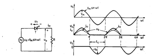
During the negative half cycle as the load current becomes zero, then SCR will turn off. If voltage exists for a period of rated turn off time of the device, then the negative polarity of the voltage across the outgoing SCR will turn it off.Here, the duration of the half cycle must be greater than the turn off time of SCR.
Thyristor Commutation Techniques
More info related Thyristor on wikipedia
More Topics
%20Commutation%20Techniques)