

Overview
So our main aim is to use goggle assistant in home automation system. But there we cannot communicate D1 mini directly with goggle assistant because the D1 mini is a very low-level IoT and goggle’s system is very high level. So we have to use some intermediate software to communicate with goggle assistant. That’s why we are used “IFTTT server”, but again the D1 mini is very low-level chip there for we used one more website to communicate with D1 mini which is “AdaFruit.com”. Now the command path is – “goggle assistant to IFTTT to AdaFruit to D1 mini”
Nowadays, the home automation system is easy to make but we are trying to make this more easier using google assistant. Whenever we connect our system with google assistant, we can give the command to the home automation system through google assistant. We used ULN IC for controlling relays.
:
- WEMOS D1 MINI • RELAYS • ULN 2003 IC (Relay Controller) • LM7805(Voltage Regulator) • Copper clad • Fecl3 Powder • CAPACITORS • SCREW TERMINALS • RESISTORS • SWITCH • DIODES • BATTERY
BROAD AREA
So our main aim is to use goggle assistant in home automation system. But there we cannot communicate D1 mini directly with goggle assistant because the D1 mini is a very low-level IoT and goggle’s system is very high level. So we have to use some intermediate software to communicate with goggle assistant. That’s why we are used “IFTTT server”, but again the D1 mini is very low-level chip there for we used one more website to communicate with D1 mini which is “AdaFruit.com”. Now the command path is – “goggle assistant to IFTTT to AdaFruit to D1 mini”
When D1 mini receives command, it will enable that particular pin which is relevant to command. And that pin is connected to the ULN2003 IC which is control the relays. So, we can switch on the relays automatically which are connected to the appliances. This is how the process is done in our “Home Automation using Goggle Assistant” system.
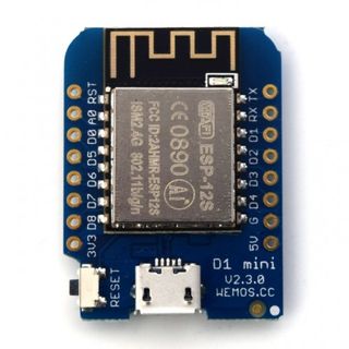
D1 MINI
The ESP8266 is a low-cost Wi-Fi microchip with full TCP/IP stack and microcontroller capability produced by manufacturer Espresso Systems in Shanghai, China. The chip first came to the attention of Western makers in August 2014 with the ESP-01 module, made by a third-party manufacturer Ai-Thinker. This small module allows microcontrollers to connect to a Wi-Fi network and make simple TCP/IP connections using Hayes-style commands. However, at first there was almost no English-language documentation on the chip and the commands it accepted. The very low price and the fact that there were very few external components on the module, which suggested that it could eventually be very inexpensive in volume, attracted many hackers to explore the module, chip, and the software on it, as well as to translate the Chinese documentation. The ESP8285 is an ESP8266 with 1 MiB of built-in flash, allowing for single-chip devices capable of connecting to Wi-Fi.

RELAYS
A relay is an electrically operated switch. It consists of a set of input terminals for a single or multiple control signals, and a set of operating contact terminals. The switch may have any number of contacts in multiple contact forms, such as make contacts, break contacts, or combinations thereof.Relays are used where it is necessary to control a circuit by an independent low-power signal, or where several circuits must be controlled by one signal. Relays were first used in long-distance telegraph circuits as signal repeaters: they refresh the signal coming in from one circuit by transmitting it on another circuit. Relays were used extensively in telephone exchanges and early computers to perform logical operations.The traditional form of a relay uses an electromagnet to close or open the contacts, but other operating principles have been invented, such as in solid-state relays which use semiconductor properties for control without relying on moving parts. Relays with calibrated operating characteristics and sometimes multiple operating coils are used to protect electrical circuits from overload or faults; in modern electric power systems these functions are performed by digital instruments still called protective relays.

ULN 2003 IC
The ULN2003 is known for its high-current, high-voltage capacity. The drivers can be paralleled for even higher current output. Even further, stacking one chip on top of another, both electrically and physically, has been done. Generally, it can also be used for interfacing with a stepper motor, where the motor requires high ratings which cannot be provided by other interfacing devices.
Main specifications (ULN 2003 IC):
⦁ 500 mA rated collector current (single output)
⦁ 50 V output (there is a version that supports 100 V output)
⦁ Includes output fly back diodes
⦁ Inputs compatible with TTL and 5-V CMOS logic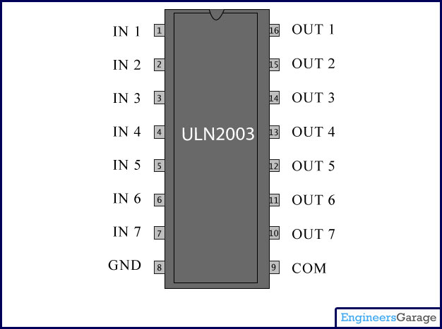
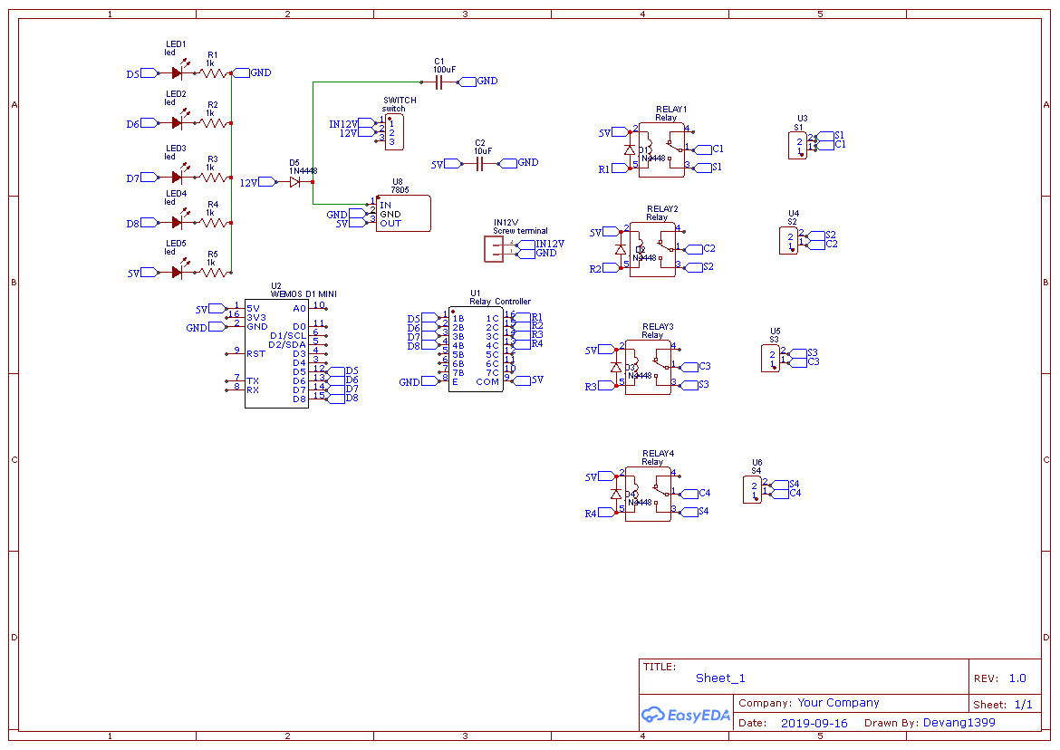
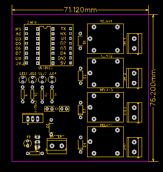
Circuit Description

We Designed our circuit using Easy EDA software. Circuit Diagram of our project is designed in schematic of easy EDA software.
Schematic Diagram :
PCB Layout :
D1 MINI CODE
#include <ESP8266WiFi.h>
#include “Adafruit_MQTT.h”
#include “Adafruit_MQTT_Client.h”
#define Relay1 D5
#define Relay2 D6
#define Relay3 D7
#define Relay4 D8
#define WLAN_SSID “Arvind” // Your SSID
#define WLAN_PASS “12345678” // Your password
/************************* Adafruit.io Setup *********************************/
#define AIO_SERVER “io.adafruit.com”
#define AIO_SERVERPORT 1883 // use 8883 for SSL
#define AIO_USERNAME “Avi_241” // Replace it with your username
#define AIO_KEY “2e8bdedbf8a64f1191ea644a9b2bf6c8” // Replace with your Project Auth Key
/************ Global State (you don’t need to change this!) ******************/
// Create an ESP8266 WiFiClient class to connect to the MQTT server.
WiFiClient client;
// or… use WiFiFlientSecure for SSL
//WiFiClientSecure client;
// Setup the MQTT client class by passing in the WiFi client and MQTT server and login details.
Adafruit_MQTT_Client mqtt(&client, AIO_SERVER, AIO_SERVERPORT, AIO_USERNAME, AIO_KEY);
/****************************** Feeds ***************************************/
// Setup a feed called ‘onoff’ for subscribing to changes.
Adafruit_MQTT_Subscribe Light1 = Adafruit_MQTT_Subscribe(&mqtt, AIO_USERNAME “/feeds/Relay1”); // FeedName
Adafruit_MQTT_Subscribe Light2 = Adafruit_MQTT_Subscribe(&mqtt, AIO_USERNAME “/feeds/Relay 2”);
Adafruit_MQTT_Subscribe Light3 = Adafruit_MQTT_Subscribe(&mqtt, AIO_USERNAME “/feeds/Relay3”);
Adafruit_MQTT_Subscribe Light4 = Adafruit_MQTT_Subscribe(&mqtt, AIO_USERNAME “/feeds/Relay4”);
void MQTT_connect();
void setup() {
Serial.begin(115200);
pinMode(Relay1, OUTPUT);
pinMode(Relay2, OUTPUT);
pinMode(Relay3, OUTPUT);
pinMode(Relay4, OUTPUT);
// Connect to WiFi access point.
Serial.println(); Serial.println();
Serial.print(“Connecting to “);
Serial.println(WLAN_SSID);
WiFi.begin(WLAN_SSID, WLAN_PASS);
while (WiFi.status() != WL_CONNECTED) {
delay(500);
Serial.print(“.”);
}
Serial.println();
Serial.println(“WiFi connected”);
Serial.println(“IP address: “);
Serial.println(WiFi.localIP());
// Setup MQTT subscription for onoff feed.
mqtt.subscribe(&Light1);
mqtt.subscribe(&Light3);
mqtt.subscribe(&Light2);
mqtt.subscribe(&Light4);
}
void loop()
{
MQTT_connect();
Adafruit_MQTT_Subscribe *subscription;
while ((subscription = mqtt.readSubscription(20000))) {
if (subscription == &Light1) {
Serial.print(F(“Got: “));
Serial.println((char *)Light1.lastread);
int Light1_State = atoi((char *)Light1.lastread);
digitalWrite(Relay1, Light1_State);
}
if (subscription == &Light2) {
Serial.print(F(“Got: “));
Serial.println((char *)Light2.lastread);
int Light2_State = atoi((char *)Light2.lastread);
digitalWrite(Relay2, !Light2_State);
}
if (subscription == &Light3) {
Serial.print(F(“Got: “));
Serial.println((char *)Light3.lastread);
int Light3_State = atoi((char *)Light3.lastread);
digitalWrite(Relay3, Light3_State);
}
if (subscription == &Light4) {
Serial.print(F(“Got: “));
Serial.println((char *)Light4.lastread);
int Light4_State = atoi((char *)Light4.lastread);
digitalWrite(Relay4, Light4_State);
}
}
}
void MQTT_connect() {
int8_t ret;
// Stop if already connected.
if (mqtt.connected()) {
return;
}
Serial.print(“Connecting to MQTT… “);
uint8_t retries = 3;
while ((ret = mqtt.connect()) != 0) { // connect will return 0 for connected
Serial.println(mqtt.connectErrorString(ret));
Serial.println(“Retrying MQTT connection in 5 seconds…”);
mqtt.disconnect();
delay(5000); // wait 5 seconds
retries–;
if (retries == 0) {
// basically die and wait for WDT to reset me
while (1);
}
}
Serial.println(“MQTT Connected!”);
}