


Introduction:
You may have seen so many applications of temperature control and indicators using different micro-controllers, microprocessors or other control devices. But what is the actual use of these temperature regulators is presented here. It controls the fan speed continuously, as the temperature varies. It is not a simple ON-OFF type control that activates the ON / OFF fan when the temperature rises / falls below a certain limit. But its continuous type controller, which continuously varies the speed of the DC fan as the temperature rises / falls. So it is a demonstration of the current industrial application.
In the industry, the fan may be AC or DC (most likely AC) or it may be cooler to reduce the temperature. As the temperature increases the fan speed increases linearly to cool it. And as the temperature drops, so does the speed. For any constant temperature, the speed remains constant.
Here is a demonstration of the same type of application. As the temperature rises from 50 oC to 150 oC, the continuous fan speed increases from min to max. Obviously, the industrial temperature range may be different for different types of applications, but it can be calibrated and programmed according to the required temperature range. At the end of the article I suggested some ideas some modifications with which the project can be used for the real industrial application for DC / AC fan speed control.
System Block Diagram:

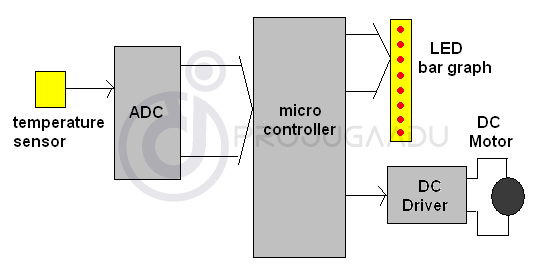
The figure shows the necessary building blocks of the system. There are temperature sensors, ADC (analog to digital converter), micro-controller, DC driver and 8 LED graphic display. Let’s look briefly at the function of each block.
Temperature sensor: is a translator. Converts temperature to equivalent electrical signal. Its output voltage increases linearly with increasing temperature. So, by measuring the output voltage, we can see a rise or fall in temperature.
ADC: because the sensor output is an analog form, it must be transformed into an equivalent digital form before being given to the microcontroller. So, the ADC converts the analog signal from the sensor into the digital signal that is given to the micro-controller.
Microcontroller: performs the following tasks
- Controls ADC and reads digital value at regular intervals
- Generates PWM and controls DC fan speed through DC driver
- Indicates the current speed on the LED bar graph display.
LED bar chart: 8-bar bar chart that shows the min speed as a lit LED and the maximum speed as all eight LEDs ON
DC driver: The direct output of the microcontroller is not capable of running the motor continuously. So the DC driver will pick up the PWM signal from the micro-controller and generate enough current to drive the DC motor through this PWM.
Selecting Suitable Microcontroller:
Now the heart of the whole system is micro-controller. Because it performs all the tasks that control the fan speed by generating PWM, indicating the speed on the LED bar graph, it reads the temperature value and turns it into digital etc. So the question is “what micro controller should I choose?” Which will perform the necessary tasks with minimal external components to reduce hardware and minimize circuitry. We have selected AVM ATMega16 AVM micro-controller. Because it built 10 bit ADC, 8 channel as well as 4 PWM channels. This exactly matches our requirements. Some of the other features of this microcontroller are
- It has 4 fully functional 8-bit I / O ports. That means a total of 32 I / O lines
- 16 KB Flash ISP
- 1KB SRAM
- 512 bytes EEPROM
- Two stopwatch / 8-bit counter and one 16-bit counter
- Real-time counter with separate oscillator clock
- Built in UART, SPI and IIC for serial communication
Programmable timer for monitoring
So if you are using ATMega16 micro-controller, you do not need to have external ADC chip. This will reduce the hardware. Also, because the built-in PWM channel is available, so you don’t need to write separate code to generate PWM. So the length of the program code will be reduced too. Overall, development time as well as cost will be reduced as well.
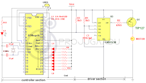
Complete Circuit:
We divided the complete circuit into two different sections
- Controller section
- DC driver section


The controller section includes the temperature sensor LM35, AVR µC ATMega16 and some discrete components such as LEDs, registers, capacitors and crystal.
Connections: – LM35 output is connected to ADC channel 0 pin (pin 40). 8 LEDs are connected to the PORTC PCO pins (22) to PC7 (29), as shown by the current limitation registers R4 – R12. Another LED (L9) is connected to the PORTB PB0 pin (1). The 8 MHz crystal along with two 33 pf capacitors are connected to pins X1 (11) and X2 (12) to provide the required clock signal. AVref together with AVcc is connected to Vcc for ADC internal operation. PWM channel output 0 The PB3 output (4) is connected to the Ic555 input trigger in the driver section.
The driver section includes the Darlington transistor type TIP127 IC555 and PNP together with discrete resistors and capacitors.
Connections: – IC555 is connected in monostable mode. Resistor R1 and capacitor C1 determine its time constants as 0.1 ms. Just reverse the available PWM output from ATMega16. Works as a HEX inversion buffer. It amplifies enough current to drive the base of the Darlington transistor. The Darlington transistor drives the DC motor through its collector, as shown.
Circuit Operation:
LM35 is a semiconductor type temperature sensor. Here are its main features
- Calibrated directly in ° Celsius (Centigrade)
- Linear scale factor + 10.0 mV / ° C
- Accuracy 0.5 ° C guaranteed (at + 25 ° C)
- Valued for between -55 ° and + 150 ° C
- It works from 4 to 30 volts
- Less than 60 μA leakage current
- Low automatic heating, 0.08 ° C in quiet air
- Non-linearity only ± 1⁄4 ° C typical
- Low impedance output, 0.1 W for 1 mA charging
Therefore, its output changes to ± 10 mV with the change to ± 1 oC. We have set the reference voltage (AVref) to 5 V. so its full-scale input voltage will be 5 V. and the resolution will be
ADC resolution = FSV / (210 – 1)
= 5 / 1024
= 5 mV (approx)
From the above calculation we can say that for every 1 oC change in temperature, the ADC output will change by 2 bits. Therefore, the ADC output is perfectly calibrated for changing the temperature oC.
The internal ADC of the ATMega16 is similar to any other available ADC external chip.
- It is first initialized with reference clock input and external reference voltage. For this, the corresponding values are loaded in the ADMUX and ADCSRA internal registers.
- Then channel 0 is selected through MUX bits in the ADMUX register.
- Then start the conversion signal is given and wait for the end of the output of the conversion signal to come out.
- A fine 10-bit output is available in ADCL and ADCH registers in HEX format.
- This HEX value is converted to a decimal equivalent. Then it is compared with any of the 8 different intervals in 50 to 150.
Depending on this value, the width of the output pulse is varied from 10% to 90%. Here we used the fast PWM generation method to generate PWM. It’s a very simple method. In this method, timer0 is initialized to generate the base frequency for the PWM. At this frequency, the OCR0 internal register counts from 0 to 255. It will count up to the value loaded in it. The number up to match the output on pin 4 is high. When the count is matched, the output becomes zero. This is repeated at each cycle. Thus, if the number in OCR0 is greater – the width of the output pulse is larger and vice versa. For example, if the value in OCR0 is 64, then the output is raised (at pin 4) until the number reaches 64. Then it becomes low for 65 to 255. Again from 0 to 64, the output is high and so on. far away.
The PWM output is given to the monostable which will simply reverse this PWM. This is why, in fact, the PWM generated by ATMega16 has a lower working cycle for a higher temperature and a lower working cycle for a lower temperature. So when reversed by IC555, it will give us the desired PWM output (it means more work cycle for more temperature and vice versa).
The width of the PWM is indicated on 8 LED bars. As the width increased from 10% to 90%, the bargraph increases from 1 LED to 8 LEDs.
Each time the micro-regulator reads the new temperature value and changes the operating cycle, it is indicated as flashing on the L9 LED.
Software Program:
The program loaded in the micro-controller is written in C language and compiled using AVR studio IDE. There are three functions and one main function.
the main function () initializes the ports and the stopwatch 0. Then, in a continuous loop, it follows
Conversion begins
Waiting for conversion to complete
Calls work to generate PWM when it gets the temperature value
Wait 2 sec
the adcinitilize () function initializes the ADC. Selects the internal clock divider and AVcc as the reference voltage AVref.
The pwm () function converts hex to ADCL and ADCH to decimal. This value is compared with any value between 50 and 150, in 8 different intervals (50-72, 73-85, etc.) and when the match is found, the value loads in OCR0 to generate PWM.
the bigdly () function generates a 200ms step delay. If the transmitted value is 10, it means that it will generate a delay of 2 seconds and so on.
Here is the complete program with the necessary approvals
/*54745756836*/)